

Regular price
€435.85
€536.10
-
 Compatible with CP5500 Pedal Box
 -
30° Measurement Range
 Compatible with CP5500 Pedal Box
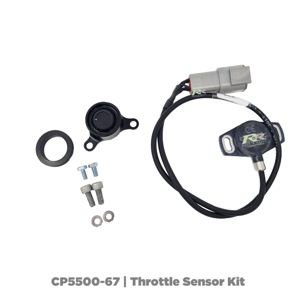
The Throttle sensor has a measuring range of 30°. This angle was selected to provide a high resolution of data from the sensor, and because the typical travel of a throttle pedal is within this. The pedal with its stops are capable of a much bigger range (20.5° forward from vertical, 27.5° backwards from vertical). The pedal box as standard will be set at 4° forward, to 24° back. If you need a different range, alter the forward stop, alter the back stop (Keep the range to within 30°), then rotate the sensor to an angle where it can read your new range.
Electrical:
- Measurement Range: 30° (both channels)
- Supply Voltage: 5 ±0.5Vdc
- Overvoltage protection: Up to 10Vdc
- Maximum supply current: <12.5mA each independent supply (<25mA total)
- Reverse polarity protection: Yes
- Short circuit protection:
- Output to GND: Yes
- Output to supply: Yes
- Power-on settlement time: <1 S
- Resolution: 0.025% of measurement range (12 Bit)
- Non-linearity*: <±0.4%
- Measured using the Least-Squares method on a computerised calibration system.
- Temperature coefficient: <±30 ppm/°C
Analog Output:
- Voltage output range Vdc: Ratiometric output voltage - 4% to 98% of Vs over measurement
- Monotonic range Vdc: 0.05 (1%) and 4.95 (99%) nominal
- Load resistance: 10k minimum (resistive to GND)
- Output noise: <1 mVrms
- Input/Output delay: <2 ms Typ.
- Output direction: Channel 1 - CW, Channel 2 - ACW
Mechanical:
- Mechanical angle: 360° continuos
- Maximum rotational speed: 3600 °/C
- Weight: <45g
- Mounting: Use 2x M4 socket head cap screws and M4 washer
- Max tightening torque 2.0Nm
- When the magnet indent mark facing toward the sensor and cable exit, the output is at mid-travel. The sensor housing allows for ±10° adjustment via the mounting flange slots.
Other:
- Cable length: 0.5m
- Electrical connections: 2x 250mm of 3-core cable: FDR-25 sheathed, with 55A spec (24AWG) cores, with 1x Deutsch DTM04-6P connectors.
- DTM Plug pin arrangement & description:
- Pin 1 (Blue) - Channel 2: +V Supply
- Pin 2 (White) - Channel 2: Output 2
- Pin 3 (Green) - Channel 2: 0V supply (GND)
- Pin 4 (Red) - Channel 1: +V Supply
- Pin 5 (Yellow) - Channel 1: Output 1
- Pin 6 (Black) - Channel 1: Ov Supply (GND)
Brand:
AP Racing
Manufacturer Part Number:
CP5500-67